Beam
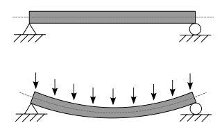


 Uniformly varying load (UVL)


A statically determinate beam, bending (sagging) under a uniformly distributed load.
WHAT IS BEAM?
A beam is a horizontal structural member in a building to resist the lateral loads applied to the beams axis. The structural member which resists the forces laterally or transversely applied to the (beam) axis is called beam.
In it, the loads are acting transversely to the longitudinal axis, which produces the shear forcesand bending moment. The lateral load acting on beams are the main cause bending of the beam. They are responsible to transfer a load from the slab to the column. The load distribution pattern is,
Slab |> Beam |> Column |> Foundation
That beam which is connected with the column and this connection is called direct support while the beam connected with beam and this connection is called indirect support.
A beam is a structural element that primarily resists loads applied laterally to the beam's axis. Its mode of deflection is primarily bybending. The loads applied to the beam result in reaction forces at the beam's support points. The total effect of all the forces acting on the beam is to produce shear forces andbending moments within the beam, that in turn induce internal stresses, strains and deflections of the beam. Beams are characterized by their manner of support, profile (shape of cross-section), length, and their material.
Beams are traditionally descriptions of building or civil engineering structural elements, but any structures such as automotive automobile frames, aircraft components, machine frames, and other mechanical or structural systems contain beam structures that are designed to carry lateral loads are analyzed in a similar fashion
A beam is a structural element that primarily resists loads applied laterally to the beam's axis. Its mode of deflection is primarily bybending. The loads applied to the beam result in reaction forces at the beam's support points. The total effect of all the forces acting on the beam is to produce shear forces andbending moments within the beam, that in turn induce internal stresses, strains and deflections of the beam. Beams are characterized by their manner of support, profile (shape of cross-section), length, and their material.
PURPOSE OF BEAMS
It is a structural element that is capable of withstanding load primarily by resisting its bending forces. They are made of steel or reinforced concrete (RCC)or steel. We use it in structure to
- Resist loads
- Counter bending moment and shear forces.
- Connect the structure together.
- Provide a uniform distribution of loads.
In the beam, the different reinforcements were used having different purposes such as
- Support bars – These bars are located in the top portion of the beam and just function to hold the stirrups in place.
- Main Bars – Provide to carry loads (Moments).
- stirrups – To counter the shear stresses (shear force).
They are generally characterized by their profile (shape, cross-section, length, material). This member of RCC structures is placed horizontally to carry the load and counter both bending and shear stresses.
The standard size of the beams,
- In a residential building is 9 ʺ × 12 ʺ or 225 mm × 300 mm according to the (IS codes).
- The minimum size of the RCC beam should not be less than the 9 ʺ× 9 ʺ or 225mm × 225mmwith the addition of slab thickness which is125mm.
PURPOSE OF STIRRUPS IN THE BEAM.
- Stirrups are used to counter the shear force. It is also called shear reinforcement in the beam.
- Shear force is maximum at the end supports (simply supported beams) and zero at the mid of the span that’s why the spacing of stirrups or rings is closed to each end supports as compared to the mid.
- Stirrups are made in a rectangular shape with reinforcement bars and which is wrappedaround the top and bottom bars of the beam.
- Sometimes, stirrups are placed diagonally andvertically to avoid the shear failure in case of cracks in beams.
Beams are traditionally descriptions of building or civil engineering structural elements, but any structures such as automotive automobile frames, aircraft components, machine frames, and other mechanical or structural systems contain beam structures that are designed to carry lateral loads are analyzed in a similar fashion.
Historically beams were squared timbers but are also metal, stone, or combinations of wood and metal[1] such as a flitch beam. Beams can carry vertical gravitational forcesbut are primarily used to carry horizontalloads (e.g., loads due to an earthquake or wind or in tension to resist rafter thrust as atie beam or (usually) compression as a collar beam). The loads carried by a beam are transferred to columns, walls, or girders, which then transfer the force to adjacent structural compression members and eventually to ground. In light frame construction, joists may rest on beams.
In carpentry, a beam is called a plate as in asill plate or wall plate, beam as in a summer beam or dragon beam.
Classification based on supports
In engineering, beams are of several types:[2]
- Simply supported – a beam supported on the ends which are free to rotate and have no moment resistance.
- Fixed – a beam supported on both ends and restrained from rotation.
- Over hanging – a simple beam extending beyond its support on one end.
- Double overhanging – a simple beam with both ends extending beyond its supports on both ends.
- Continuous – a beam extending over more than two supports.
- Cantilever – a projecting beam fixed only at one end.
- Trussed – a beam strengthened by adding a cable or rod to form a truss.
TYPES OF LOADS ON BEAMS
1: Point load or concentrated load
The point load is defined as a load applied on a single location of the whole span length.
- It is also called a concentrated load.
- Act over a small distance.
- The load is denoted by P and the arrow shows the load direction.
2: Distributed Load:
This load is divided into two main loads such as,
Uniformly distributed load (UDL)
The loading magnitude remains the same to the whole span called uniformly distributed load.
- It is denoted by q or w.
Uniformly varying load (UVL)
The load whose magnitude is continuously varying throughout the span.
- It is also called a non-uniformly distributed load.
- It is also divided into two further typesTriangular or Trapezoidal Load.
3: Couple Forces
This force act on the same span haing the same load and opposite forces.
- In case of unequal load, the one force make them to rotate.
- Expresses as kip.m, kg.m, N.m, lb.ft etc.
REINFORCEMENT IN RCC BEAM
1: Single reinforcement
The reinforcement is provided in the tension zone called a single reinforcement beam.
- Responsible to carry ultimate bending moment and tension.
- Compression is counter by concrete.
- Practically this is not applicable.
- in which applied of only slab.
Area moment of inertia
In the beam equation I is used to represent the second moment of area. It is commonly known as the moment of inertia, and is the sum, about the neutral axis, of dA*r^2, where r is the distance from the neutral axis, and dA is a small patch of area. Therefore, it encompasses not just how much area the beam section has overall, but how far each bit of area is from the axis, squared. The greater I is, the stiffer the beam in bending, for a given material.

Diagram of stiffness of a simple square beam (A) and universal beam (B). The universal beam flange sections are three times further apart than the solid beam's upper and lower halves. The second moment of inertia of the universal beam is nine times that of the square beam of equal cross section (universal beam web ignored for simplification)
Stress
Internally, beams subjected to loads that do not induce torsion or axial loading experiencecompressive, tensile and shear stresses as a result of the loads applied to them. Typically, under gravity loads, the original length of the beam is slightly reduced to enclose a smaller radius arc at the top of the beam, resulting in compression, while the same original beam length at the bottom of the beam is slightly stretched to enclose a larger radius arc, and so is under tension. Modes of deformation where the top face of the beam is in compression, as under a vertical load, are known as sagging modes and where the top is in tension, for example over a support, is known as hogging. The same original length of the middle of the beam, generally halfway between the top and bottom, is the same as the radial arc of bending, and so it is under neither compression nor tension, and defines the neutral axis (dotted line in the beam figure). Above the supports, the beam is exposed to shear stress. There are somereinforced concrete beams in which the concrete is entirely in compression with tensile forces taken by steel tendons. These beams are known as prestressed concretebeams, and are fabricated to produce a compression more than the expected tension under loading conditions. High strength steel tendons are stretched while the beam is cast over them. Then, when the concrete has cured, the tendons are slowly released and the beam is immediately under eccentric axial loads. This eccentric loading creates an internal moment, and, in turn, increases the moment carrying capacity of the beam. They are commonly used on highway bridges.

The primary tool for structural analysis of beams is the Euler–Bernoulli beam equation. This equation accurately describes the elastic behaviour of slender beams where the cross sectional dimensions are small compared to the length of the beam. For beams that are not slender a different theory needs to be adopted to account for the deformation due to shear forces and, in dynamic cases, the rotary inertia. The beam formulation adopted here is that of Timoshenko and comparative examples can be found in NAFEMS Benchmark Challenge Number 7.[4] Other mathematical methods for determining thedeflection of beams include "method of virtual work" and the "slope deflection method". Engineers are interested in determining deflections because the beam may be in direct contact with a brittle material such asglass. Beam deflections are also minimized for aesthetic reasons. A visibly sagging beam, even if structurally safe, is unsightly and to be avoided. A stiffer beam (high modulus of elasticity and/or one of higher second moment of area) creates less deflection.
Mathematical methods for determining the beam forces (internal forces of the beam and the forces that are imposed on the beam support) include the "moment distribution method", the force or flexibility method and the direct stiffness method.
General shapes
Most beams in reinforced concrete buildings have rectangular cross sections, but a more efficient cross section for a beam is an I or H section which is typically seen in steel construction. Because of the parallel axis theorem and the fact that most of the material is away from the neutral axis, the second moment of area of the beam increases, which in turn increases the stiffness.

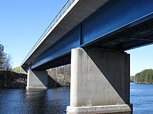
An I shaped beam of metal under a bridge
An I-beam is only the most efficient shape in one direction of bending: up and down looking at the profile as an I. If the beam is bent side to side, it functions as an H where it is less efficient. The most efficient shape for both directions in 2D is a box (a square shell) however the most efficient shape for bending in any direction is a cylindrical shell or tube. But, for unidirectional bending, the I or wide flange beam is superior.[citation needed]
Efficiency means that for the same cross sectional area (volume of beam per length) subjected to the same loading conditions, the beam deflects less.
Other shapes, like L (angles), C (channels) or tubes, are also used in construction when there are special requirements.
Thin walled
A thin walled beam is a very useful type of beam (structure). The cross section of thin walled beams is made up from thin panels connected among themselves to create closed or open cross sections of a beam (structure). Typical closed sections include round, square, and rectangular tubes. Open sections include I-beams, T-beams, L-beams, and so on. Thin walled beams exist because their bending stiffness per unit cross sectional area is much higher than that for solid cross sections such a rod or bar. In this way, stiff beams can be achieved with minimum weight. Thin walled beams are particularly useful when the material is acomposite laminate. Pioneer work on composite laminate thin walled beams was done by Librescu.
The torsional stiffness of a beam is greatly influenced by its cross sectional shape. For open sections, such as I sections, warping deflections occur which, if restrained, greatly increase the torsional stiffness.
Construction of beam
Different types of beams are used in construction of building and structures. These are horizontal structural element that withstand vertical loads, shear forces and bending moments. Beams transfer loads imposed along their length to their end points to walls, columns, foundations, etc.
In this article, different types of beams used in building construction will be discussed based on their manner of support, cross-section shape (profile), length, and their material.
Types of Beams in Constructions
There are different types of beams which are classified based on the following
- Based on Support Conditions
- Based on Construction Materials
- Based on Cross-Section Shapes
- Based on Geometry
- Based on Equilibrium Condition
- Based on Method of Construction
- Others
Based on Support Conditions
1. Simply Supported Beam
It is the one of the simplest structural elements that both ends are rest on supports but are free to rotate. It contains pinned support at one end and roller support at the other end. On the basis of assign load, it sustains shearing and bending.
Fig. 1: Simply supported beam
2. Fixed Beam
It is supported at both ends and fixed to resist rotation. It is also called a built-in beam. The fixing.
3. Cantilever Beam
If a beam is fixed at one end and set to be free at the end, it is termed as cantilever beam. The beam distribute the load back to the support where it is forced against with a moment and shear stress. Cantilever beams allow the creation of a bay window, balconies, and some bridges.
Fig. 3: Cantilever beam
4. Continuous Beam
A continuous beam has more than two supports distributed along its entire length.
Fig. 4: Continuous beam
Based on Construction Materials
5. Reinforced Concrete Beams
It is constructed from concrete and reinforcement as shown in Fig. 5.
6. Steel Beams
It is constructed from steels and used in several applications.
Fig. 6: Steel beam
7. Timber beams
This type of beam is constructed from timber and used in the past, but its application is significantly declined now.
Fig. 7: Timber Beam
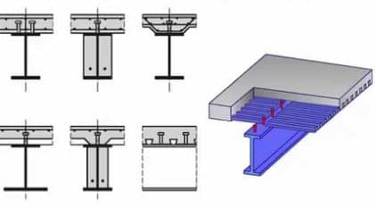
8. Composite Beams
Composite beams are constructed from two or more different types of materials such as steel and concrete, and various valid cross sections have been utilized as shown in fig.8.
Fig. 8: Composite beam


No comments:
Post a Comment